|
Copyright ©2011 by Paul Niquette. All rights reserved. |
||||||||||||||||||||||||||||
 The
geometrical
relationships postulated in the puzzle,
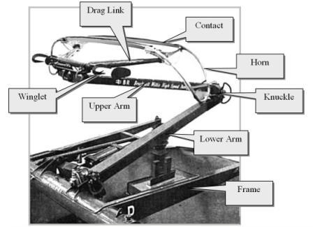
are quite elementary. The upper arm is six feet in
length and reaches vertically from the 'knuckle" a
distance of three feet to the contact wire. The
angle between the arm and the contact wire must be about
30o. The aerodynamic drag
force of the structure -- let's call it fDRAG -- is shown in
the sketch below acting along the contact wire. We
see fDRAG depicted as the hypotenuse
of a right triangle, resolved into two components. The
geometrical
relationships postulated in the puzzle,
are quite elementary. The upper arm is six feet in
length and reaches vertically from the 'knuckle" a
distance of three feet to the contact wire. The
angle between the arm and the contact wire must be about
30o. The aerodynamic drag
force of the structure -- let's call it fDRAG -- is shown in
the sketch below acting along the contact wire. We
see fDRAG depicted as the hypotenuse
of a right triangle, resolved into two components.
The compression force in the upper arm is given by fCOMPRESSION = fDRAG cos 30o but has no particular relevance to the solution. The "lifting force" points generally upward -- opposite to the weight of all the pantograph components. By simple trigonometry, fLIFT = fDRAG sin 30o = fDRAG / 2.
Aerodynamic drag
force increases according as the square of
speed. Taking the indicated ratios of cruise
speeds in the table, with 50 mph as a base, the
solutions are derived directly...
Solvers should take notice of an especially sensitive parameter -- the elevation of the contact wire. The height given in the puzzle was three feet above the "knuckle," resulting in an angle of 30o between the contact wire and the upper arm. If the contact wire at some point along the trackway were to be elevated higher by, say, 1'-3", that angle will increase to 45o, and each of the lifting forces derived in the solution table will be increased by sin 45o / sin 30o (1.414). Accordingly, the V150 traveling at 350+ mph at that site will have a lifting force fLIFT > 554 lbs.
With the train stopped, the control system supplies an upward force of about 280 lbs, which balances the weight of the pantograph itself plus the force against the contact wire overhead. The aerodynamic drag force is zero. As the train moves along the trackway, the red curve shows how the control system must supply an increasing upward force to overcome an aerodynamic drag force in the downward direction caused by the "knuckle" facing forward. The bluecurve shows that control system produces a decreasing upward force as the train speeds up causing the contact head to develop a "lifting force," in effect reducing the load on the pantograph control system. Feedback for assuring appropriate contact wire force (20-40 lbs) is derived from load cells built into the pantograph head. Notice that at about 220 mph, the control system is required to produce no upward force at all, as the pantograph head is, in effect, 'flying' along the contact wire. At trains speeds above 220 mph, the control system must apply a negative -- downward -- force on the pantograph head. The magnitude of that force can reach into the hundreds of lbs. If not reliably assured by the servomechanism in the pantograph control system, such a force would result in a horrendous upward impact on the contact wire resulting in demolition of the overhead structure for miles of trackway before the train can be stopped! The Pantograph Design must include fail-safe provisions. Imagine what might occur if the control system or its power supply fails. One option is to spring-load the lower arm in the downward direction. In powering up the train in the yard, a dedicated actuator moves the lower arm up into its fixed operating position, where it is latched. When a failure is detected, the system releases the latch and the lower arm drops away under the force of the spring, taking down the contact head. By the way, disconnected from its overhead supply, the train loses more than its traction power. It will become dependent upon batteries to supply its "hotel power" and also to energize various control systems -- including the subsystem that raises the pantograph. A light rail train, of course, can get by with a simple, spring-loaded configuration to apply a nearly constant 280 lbs of lifting force. As shown here, though, the Pantograph Design for a high-speed train is quite complicated.
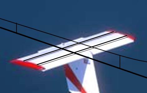
 Let us address the subject of aerodynamic drag coefficient. The picture below depicts an imaginary application of aircraft fairing technologies in the Pantograph Design. It is easy to show that by surrounding the pantograph head structure inside a fairing made of, say, fiberglass, the drag coefficient might be reduced by a factor of as much as 20-to-1. Accordingly, even the highest speed train, the V150, would not need to manage aerodynamic forces greater than 40 lbs.
Solvers are cordially invited to submit their favorite idea for a Pantograph Design for publication here. |
 The graph on the right plots the force
supplied by the control system required to balance all
the forces acting on the pantograph as a function of
train speed.
The graph on the right plots the force
supplied by the control system required to balance all
the forces acting on the pantograph as a function of
train speed.