|
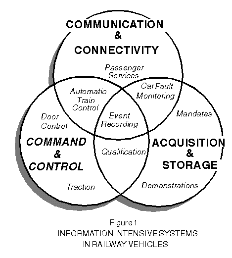
Abstract: Higher speeds and closer headways place increasing demands on information intensive systems in railway vehicles and wayside systems. Many are classified as 'vital' -- a term of art which denotes stringent criteria for assuring safety. Intelligent Distributed Control (IDC) with its decentralized architecture, ultra-high levels of integration, combined with realtime software and Local Operational Networks is well suited to the support of command and control, data acquisition and storage, communication and connectivity. This paper will focus on smart sensor requirements that exploit IDC's properties to achieve vital design, fault tolerant control methodologies as well as non-invasive signalling on simplified intra-vehicular wiring and via existing trainlines throughout the 'consist.' Information Intensive Systems Railway services and systems have become -- like almost any other you can name -- information intensive. The expression relates to problems, to solutions, to technologies, and to products. The railway industry has come to recognize that both onboard and wayside systems stand to benefit richly from the so-called 'information payoffs.' When asked by railroading people, "What do you mean by 'information intensive'?" I have found the following three categories to be useful:
Railway operations will not tolerate frequent service interruptions. But equipment reliability is not enough. Faults themselves have to be tolerated. Subsystems that command the train to move or to stop, doors to open or to close must meet stringent -- vital -- safety criteria: Failures cannot result in hazards. But redundancy is not enough. Faults must not be concealed. To support both availability and safety, equipment defects must be predicted and prevented. Thus, for command and control applications, information intensive systems answer the highest calling. Sensor subsystems have a considerable independence in their local, event-driven processes, but they must exchange signals with one another -- often vitally. Information intensive systems in locomotives and transit vehicles have resulted in a bulky labyrinth of wiring. Reliability in delivering sensor data means assuring that the receiver gets each message before the sender gives up 'foreknowledge and control.' In railway applications such requirements have not been supported by conventional, 'hardwired' connections. Re-routing of sensor signals may become necessary, which means breaking connections and making new ones. The subject of information intensity becomes especially interesting in the collaboration among these fundamental requirements. Trains must make their way along trackage owned by various properties; here the term 'interoperability' has become especially meaningful. Railway vehicles are being equipped for acquiring sensor data and storing measurements, traditionally for offline analysis. Increasingly, systems are expected to perform online analysis. A form of 'expert system' is emerging, which not only carries out data reduction in realtime but applies algorithms that guide operational decisions. Applying IDC architecture for monitoring and interpreting smart sensors will serve a number of information intensive business needs. Energy management is a big one. Others include eliminating service interruptions, reducing time-to-repair, transforming corrective maintenance into preventive procedures, supplanting time-based or mileage-based parts replacement with maintenance practices supported by online measurements of wear and deterioration, thereby improving operational policies and training. Network Architecture Until recently, information intensive subsystems onboard railway vehicles relied on hardwired connectivity and, to the extent that such existed, highly centralized information processing architecture. Railroads have come to recognize that ultra high levels of circuit integration in microelectronics makes it possible to carry out complex information processing in small, economical nodes. The industry has become receptive to the application of connectivity via 'Local Operational Network' (LON), by which intelligent nodes 'interoperate,' exchanging data peer-to-peer.
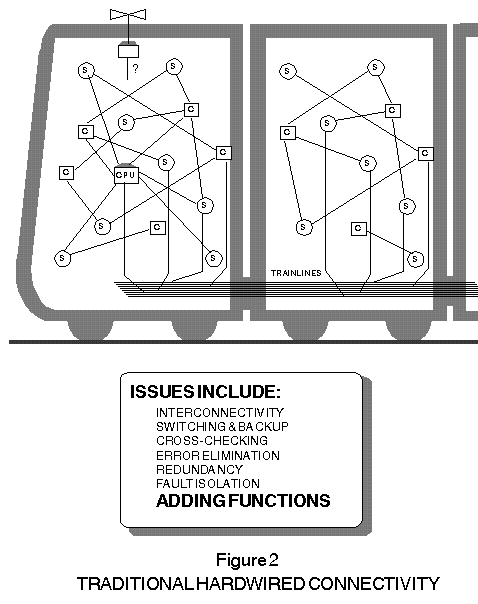
In Figure 2, we see a traditional railway 'consist' with subsystems, each comprising various sensors (S) and controllers (C), all hardwired together and, in some cases, to CPUs, which are typically located in the lead car. Dozens of 'trainlines' -- up to a hundred or more, in some cases -- are shown carrying signals from car to car. A number of technical issues are listed in Figure 2. Interconnectivity demands the installation of many miles of wiring in conduits and cable troughs, each conductor dedicated to a specific signal, often operating at extremely low data rates (for example, 'doors closed' requires no more than one bit per minute). Switching and backup add dedicated wiring and devices (cutouts and bypasses), incremental complexity that subverts reliability and often requires service interruption for manual intervention. Likewise, cross-checking calls for additional equipment, multiple CPUs in some cases. Without forward-correcting codes or acknowledged signalling, error elimination may not be possible. Redundancy means twice or thrice the equipment; the alternative (coded redundancy) is not supported by bit-per-wire signalling protocols. Fault isolation generally calls for re-routing of signals, which is difficult if not impractical to support in non-network architectures. Finally, there is the onerous problem of adding functions (for example retrofitting a wireless data-download capability as depicted in Figure 2).
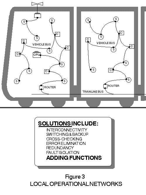
As shown in Figure 3, Intelligent Distributed Control (IDC) associates a microprocessor-based node with each sensor (S) and with each controller (C). The railway industry has come to accept the idea of 'sensors-made-smart' through association with nodes that support embedded software, directly and locally managing all processes associated with acquiring sensor information. These event-driven processes include 'over-sampling' to eliminate 'aliasing' (locally acquiring measurements at a high rate compared to that which characterizes the ability of the signal to change), performing comparisons against limits in magnitudes and in rates of change, assigning time stamps for aging measurements and for subsequent deskewing of samples, predicting out-of-range condi- tions, and addressing relevant data to other nodes on the LON. Likewise, a controller node has embedded software that directly and locally manages the subsystem to which it is attached. These, too, are event-driven algorithms that adapt to and take action on data received from one or more smart sensor nodes. In Figure 3, then, we see a consist with its subsystems architected for IDC: sensors-made-smart by networking via nodes operating controllers-made- smart. For railway applications -- both freight and transit -- two types of LONs are preferred. A 'vehicle bus' is indicated as connecting the nodes to one another within a given railway vehicle. A 'trainline bus' connects nodes together throughout the consist. MK has adopted a topology-free twisted pair network to serve as the vehicle bus and a power line LONWORKS for the trainline bus. It should be emphasized that the latter can be overlaid to send messages along the consist over existing trainlines while neither interfering with the signalling already in place nor suffering degradation from those signals. In between the vehicle bus and the trainline bus are 'network routers.' Since the protocols of both the vehicle bus and the trainline bus are the same, each router serves as an intelligent `bridge,' unburdened by 'gateway' overhead. A number of technical solutions are listed in Figure 3 -- the same items, in fact as those characterized as technical issues in Figure 2. Interconnectivity takes the form of node-resident software that establishes signalling pathways such that data packets flow transparently node-to-node over the LONs. The nodes themselves administer the requisite logic to assure reliable, peer-to-peer communications. The application software running within each smart sensor node stores data measurements in its local memory as 'network variables,' which automatically re-appear in the local memory of each node that requires the measurement. The connections are put in place by means of a software procedure called 'binding,' which effectively takes the place of point-to-point wiring. It is worth noting that a smart sensor node can communicate with other smart sensor nodes as well as with controller nodes. This provides support for switching and backup, which can take place within node software; same for cross-checking and error elimination. There is nothing to be gained by applying 'leader/follower' schemes; moreover, the smart sensor nodes support forward code checking and acknowledged transmissions where appropriate. These processes are seamless and robust -- and transparent to the node software supporting individual applications. Redundancy in signalling can take the form of appropriate combinations of multiple nodes, parallel networks, and coded redundancy. Fault isolation calls for software rerouting of signals, an approach made practical by the LONWORKS architecture. Finally, there is the matter of adding functions. This can be readily accomplished with minimal additional wiring within a vehicle and with overlay signalling on existing trainlines. Thus, for communication with the wayside, a wireless subsystem can be integrated into the network as indicated in Figure 3.
Data packets transmitted by smart sensor nodes flow through a 'vehicle bus,' a topology-free, shielded-twisted-pair LONWORKS network. For signalling throughout the consist IDC makes use of 'overlay' signalling superimposed on existing trainlines (intercom or public address, say) without interfering with the communication signals already present. Overlay transmissions use a spread-spectrum carrier with forward error correction for highly reliable signal delivery. The vehicle bus uses differential Manchester coded signalling technology at the physical layer. Each node is equipped with a transceiver having three on-chip microprocessors programmed in firmware for the support of all seven layers of the Open System Interconnect model (physical, link, network, transport, session, presentation, application). The protocol is LONTALK, a trademark of Echelon Corporation. It is being adopted as a defacto standard by other industries and is well suited for onboard signalling needs of the railroads. {FootNote 1}
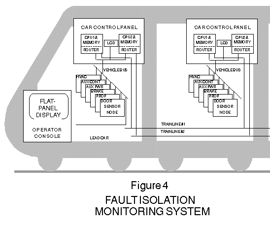
Vehicle Health Monitoring Intelligent Distributed Control (IDC) makes all sensors smart. Whether processing power is integrated into the sensor itself or partitioned into associated nodes is an option for product planners and system integrators. In some cases, receiving or controlling devices will need a greater share of the intelligence. Where safety and availability dominate, where redun- dancy and cross-checking are mandated, where backup and recovery are essential, the sensor may or may not be invested with all the smarts. An illustration of an IDC approach to vehicle health monitoring is summarized in Figure 4. The Fault Isolation Monitoring System (FIMS) was designed as part of a transit vehicle remanufacturing program. Similar systems are being produced and installed on existing vehicles in retrofit programs, where the emphasis, of course, is to simplify and to hasten installation. In either case, the system integrator is motivated to minimize vehicle wiring and, especially for retrofit programs, to make full use of an overlay signalling technology, such as that enabled by Echelon products and supported by LONWORKS products. For fleet compatibility, FIMS-equipped vehicles must operate -- interoperate -- in consists that include non-FIMS vehicles, a requirement that forbids any change in the trainline signalling. FIMS makes extensive use of down-stream intelligence, which is not to say that the monitoring systems are necessarily precluded from the benefits offered by smart sensors. For vehicle health, no doubt some of the nodal processing could be integrated into sensor products. That's because the mission is 'non-vital.' All monitored data is acquired via 'high impedance' sensors, which are mandated not to interfere with vehicle systems. The fault and operating information captured by FIMS will improve maintainability of new and existing vehicle systems by capturing relevant information about the operation of each onboard system, and by providing application-specific database management tools, which can be evolved to support expert sys- tems for failure pattern analysis and expanded over time to include the logging of additional measurements for fault prediction. Major subsystems of the FIMS are depicted in Figure 4. Each vehicle has one car control panel and six sensor nodes in strategic locations throughout the vehicle (shown for illustrative purposes in Figure 4 as associated with their respective systems). The car control panel comprises two independent CPUs, each with memory for data storage. A lead/tail car has one operator console node, which supports a flat-panel display. All nodes within a given car operate peer-to-peer over a vehicle bus and from vehicle to vehicle throughout the consist by overlay signalling via dual-redundant -- existing -- trainlines.
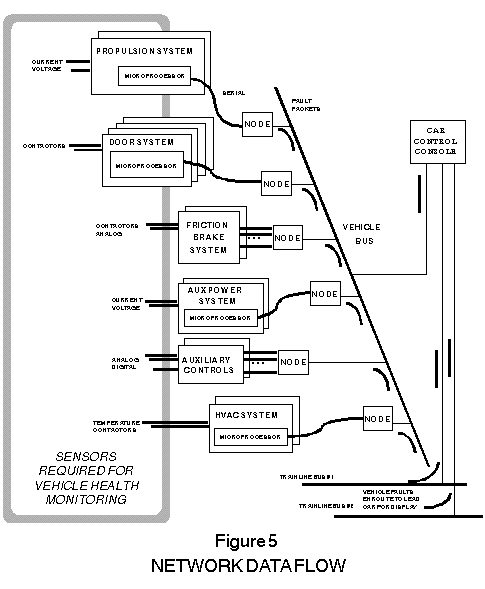
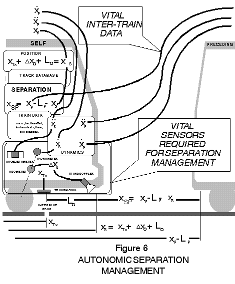
Figure 5 summarizes the principal flow of data within a typical transit vehicle. The sequence begins at a sensor associated with vehicle subsystems. Some sensors, of course, are a required part of the subsystem; others are FIMS-specific. The former are accessed serially from subsystem microprocessors by FIMS; the latter may be raw digital, analog, or temperature measurements, which are received by a data acquisition channels on a sensor node. Railroad electrical environments are notoriously hostile. The sensor node isolates and limits every signal, applies hysteresis and thresholding. Microprocessors in the sensor node prepare a performance or fault message packet for transmission peer-to-peer to the car control panel. Both CPUs in the car control panel independently collect the data for storage in memory under the control of an event-driven algorithm. Software in the car control panel also analyzes faults in logical combinations to identify a fault (a door being open is not a fault -- unless the train is moving) and the misbehaving system (an apparently inoperative HVAC unit may be the result of an auxiliary power failure). Two separate memories, each capable of storing large amounts of performance data, are independently controlled in the dual CPUs. The LCD display in the car control panel provides visual indications of current vehicle faults accessible to service technicians via a locked access panel. Moreover, the FIMS network supports accessing information about every car in the consist from any car in the consist. The same performance or fault information packets issued by all sensor, are received in parallel by each of two network routers in the car control panel and re-transmitted peer-to-peer by dual redundant trainlines to the routers in the car control panel in the lead vehicle. There, the network protocol supports re-transmission of the data via vehicle bus to the operator console node. Fault and operational information is formatted locally for immediate presentation on the train operator's display. In like manner, the operator console node located in the tail car, which has constant access to all communications traffic over the dual-redundant trainlines may serve as a backup to the operator console node in the lead car. The architecture embodied in this design applies and exploits LON signalling protocols throughout the FIMS that enable exceptionally powerful IDC mechanisms. Expressions such as 'master/slave,' 'leader/follower,' and 'primary/secondary' have no applicability. {FootNote 2} The dual redundant architecture provides backup in continuous form. The decision about which source will be actually adopted for logging or annunciation is made by the microprocessor ensemble within the downstream node based on an IDC algorithm implemented in its application software. Further to the point about decentralized architecture, the car control panel is equipped with two separate routers, one for each trainline bus. Information flowing from within the vehicle toward the lead car (see Figure 5) passes from the vehicle bus into the twisted-pair transceiver of two routers, each of which is a double node connected digitally back-to-back fully capable of IDC functionality as well as supporting the trainline bus to which it is connected. Each trainline bus uses spread spectrum signalling technology at the physical layer, a significant difference from that appearing on the twisted pair vehicle bus: the trainline transceiver is capable of reliably transmitting and receiving signals superimposed upon existing trainlines while neither interfering with the signals already present nor experiencing logical degradation from the signals that are already present. The technology has been qualified using both common and differential excitation via existing trainlines on operating trains, including end-to-end signalling on several transit properties such as Bay Area Rapid Transit District (a 10-car consist), Metro North Commuter Rail, Chicago Transit Authority -- even including a 36-car ore train at Henderson Mine. Many millions of packets have been thus delivered error free. The requisite powerline transceiver supports the seven layers of the OSI model, making FIMS into a logically coherent whole throughout the consist, with built-in support for error detection and correction. The application layer in each router, by the way, is programmed to share in the logical interpretation of data as part of the IDC architecture in addition to performing its nominal functions as a repeater and inter-network bridge. Throughout the FIMS, therefore, communications are implemented by means of network variables (NV). Specific performance or fault data from a system in any given car in the consist can be temporarily stored as a NV in one of its Local Data Acquisition Nodes sensor node. Based on binding parameters, the packet containing that NV will be transparently delivered to any other designated node or nodes onboard the train in one or another of the optionally specified modes, including broadcast and point-to-point, with security features as appropriate along with message authentication. The network processors within the receiving node or nodes detect changes in the NV upon arrival, calling event-driven software algorithms into operation. There is no need, for example, to designate one FIMS device to take control of the data buses either under normal operations or as a consequence of trainline or subsystem failure. Instead, both CPUs simultaneously receive and act on all relevant data, storing performance data and fault events in separate memories. The failure of a single CPU within a car control panel, therefore, does not jeopardize the capturing of data into memory. Redundant support for the dual-redundant trainline buses is likewise provided in the FIMS -- even achieving the effect of a contemporaneous crossbar. Railroad operations demand availability as well as safety. The twin antagonists, 'missed threat' and 'false alarm,' stalk the management corridors. Thus the vehicle health monitoring systems will report faults in train systems -- most significantly, they will predict faults in train systems. Still, not every state change signifies an incipient fault, not every steady signal means normal operation. Algorithms detect subtle changes in parameters and interpret their meaning, both combinatorially and sequentially. Unchanging values must be viewed with suspicion, too. In making sensors smart, then, passage of time participates in the online logic for detecting stuck conditions. For lost signals attributable to connectivity faults, that logic might best reside in down-stream devices, not in the sensor itself. To fulfill its mission perfectly, the vehicle health monitoring would have to be above reproach. A more realistic expectation is that, for reporting the preponderance of faults in train systems, it should generally not conceal its own. That's what self test is about. The pre-dispatch testing of train systems, either automatically or semi-automatically, does not, strictly speaking, fit into the 'self-test' category. Testing the train systems is indeed what vehicle health monitoring systems are about. Safety is, of course, a sine qua non; however, service holds primacy. Vehicle health monitoring relates to safety -- but only retrospectively. Still, some adverse indications have the power to take a train out of service. Safety need not be put in doubt if certain failure indications occur while the train is underway, and operating procedures permit completion of the current mission with a redundant or non-critical system disabled (`cutout'). Accordingly, vehicle health monitoring must be strongly biased against the 'false alarm.' Again, the independent variable, 'passage-of-time,' plays an essential role -- in this case, disqualifying short-term indications ('glitches'). Vehicle health monitoring relies on individual sensors and wired connections from them. Dual or triple redundancy will generally be warranted based more on false alarm than on missed threat. Indeed, a given 'fault' may actually be a defective sensor or an open connection to the monitoring system itself. Here again, algorithms that cut across subsystems will make the correct diagnosis in many cases (no traction-motor current, yet the train is moving). Extending 'self test' by equipping smart sensors with onboard signal injection would not be justified for vehicle health monitoring and in some cases they may be hazardous. As shown with FIMS, vehicle health monitoring is characterized by 'non-invasive' sensing of operating parameters. Dual redundant architecture and down- stream intelligence assures the delivery of performance and fault data for logging and maintenance actions. Reliability is important, but vehicle health monitoring does not in and of itself jeopardize safety. Train Control Train control is a different matter. Information from sensors must participate in algorithms which result in commands to traction motors, brakes, and doors. One of the safety-critical applications for sensors in railroading is separation management. Current train control systems -- freight or passenger, manual or automatic -- rely on 'block signalling,' by which separation is assured under the online influence of a centralized authority arranged to allow only one train at a time to occupy a given block (a segment of track of fixed length). Information about the location of trains is crudely quantized based on train length and the size of each block. Information about the speed of trains is nil; accordingly, in authorizing train movements for a given train, the centralized system necessarily assumes zero for the speed of the immediately preceding train. That assumption is called the 'brickwall.' In rapid transit, which is characterized by grade-separated right-of-way, service may be calibrated by two parameters: travel time and waiting time. Travel time is limited by train dynamics, frequency of stops, and dwell times. Waiting time or inter-arrival interval has a term-of-art: 'headway.' Improving headways will increase transit system productivity -- even more than running trains at higher speeds -- while requiring a mere fraction of expenditures attendant to building more physical plant. Considered in pairs, headway is determined by the ratio of distance between respective lead cars to the instantaneous speed of the following train (self in Figure 6). Safety mandates non-zero spatial separation between self and preceding based on First Principles (solid objects have finite size; two solid objects cannot occupy the same space at the same time). Then too, spatial separation must be commanded indirectly limited by other First Principles (objects with mass cannot change speed instanta- neously; energy cannot be created nor destroyed). In particular, the speed of self must be upperbounded by commensurate stopping distance relative to the instantaneous space between its lead car and the tail car of preceding. Speed likewise is necessarily commanded indirectly as acceleration or deceleration, in turn a consequence of 'tractive effort' and 'brake effectiveness' exerted upon applicable train mass, limited ultimately by energy considerations.
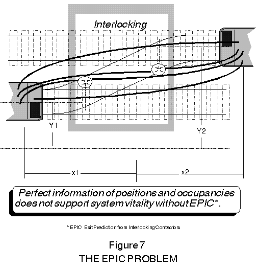
In summary then, both headway minimization and safe separation are self's responsibility. Early and current train control systems, both manual and automatic, rely on centralized authorizations from wayside stations generally over landline signalling to regulate train movements. 'Autonomic Separation Management' is our term for a system which fully exploits intelligent distributed control (IDC) applied to the train as a whole and which derives its meaning from advantages already enjoyed in natural systems under that name (spinal ganglia): an autonomic system will be capable of taking appropriate action remotely with no reliance on round-trip signalling pathways to and from a centralized authority. Now, 'automatic' applies to primitive devices like toasters and toilets. The term 'autonomous' connotes total independence (as in sovereign nations), which is not an appropriate concept for train control, inasmuch as train movements must be coordinated to accommodate track convergence and divergence, and information vital to safety is available only from the wayside, in particular, sensors at interlockings (see Figure 7).
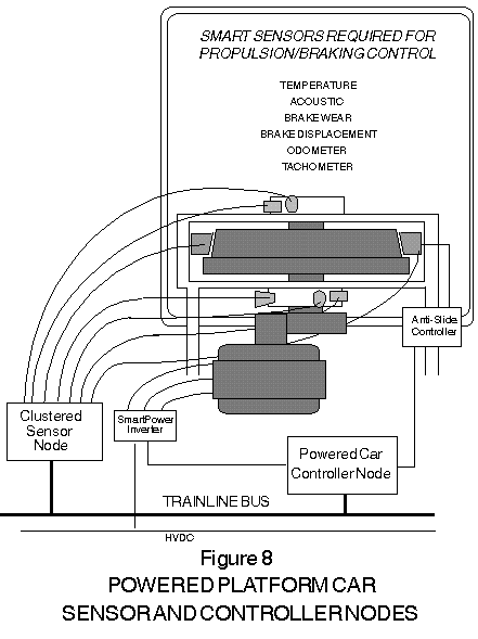
In order to control its own traction/braking, self needs dynamical information, all of which is readily available from onboard sensors and memory devices. There would seem to be no intrinsic value in a system fashioned to send all that information to the wayside for the solitary purpose of gaining access to computing power shared with other trains; for we know that to do so imposes unreliabilities and loop delays in the pathways that eventually must return speed commands. Moreover, having online knowledge of one additional spatial variable, location of preceding's tail car, self can maintain separation, although not minimal separation. For determining self's own location, a combination of technologies come into consideration, which would include spread-spectrum radio-ranging, de-dithered Global Positioning System (GPS) -- outside tunnels, of course -- augmented by deductive reckoning (the original source for the unfortunate contraction, 'dead reckoning'), re-calibrated at stations or when passing a wayside beacon -- even at impedance bonds where track signals change. Another promising smart sensor is shown in Figure 6: 'TransDoppler,' which provides precise odometry referenced to the track not the wheel. All these sensing methods are practical and retrofitable. As indicated in Figure 6, preceding's position and train-length can be transmitted over wireless network and received by self. The next -- and most beneficial embellishment -- is to provide self with realtime access to preceding's speed, presumably as messaged over the same radio link. By the way, under autonomic separation management, a train having equal-or-less mass and equal-or-greater braking effort can safely follow another with a headway equal-or-greater than the system loop delay, which may be only a matter of seconds. Finally, with access to preceding's instantaneous acceleration (deceleration, actually, a one-bit version of which is the electronic equivalent of a 'brakelight'), self can, under a predictive algorithm, assure the minimum safe separation for a wide range of relative dynamical parameters. All of the requisite sensors, signalling, and processing devices are derived from proven commercial technologies, as are the accompanying software methodologies. Sensor nodes, some with built-in intelligence, play an important role in the architecture of autonomic train separation. Furthermore, there are daunting safety requirements that characterize railroading applications. Railway vehicles with their traditional wiring harnesses suffer limitations in supporting vital control functions. The challenge is to apply IDC to achieve vitality. All trains are electric. Apart from lightning, however, electricity is not a source of energy. Whether obtained from wayside power stations or head-end prime movers, electric propulsion serves as the 'transmission' -- managing the speed/torque reciprocity. Solid state devices capable of high-power switching are enabling ac propulsion to dominate new railroad applications. The dividing line between 'electronic' and 'electric' has become diffused. Tractive effort can be intelligently regulated with ac propulsion, avoiding costly 'wheel slips.' Likewise, regenerative braking can be managed to prevent 'wheel slides' and their consequent flat-spots. Both require smart sensors for wheels and gear boxes. A new train wheel starts at, say, 32 inches in diameter and, through 'conicity' gradually wears down by an inch or more. The frequency of ac propulsion must be accurately matched to the wheel rotation speed and cannot be applied commonly to wheels that differ significantly in diameter. As shown in Figure 8, ac propulsion will doubtless benefit greatly from decentralize control architecture. {FootNote 3}
Future propulsion systems for both freight and passenger rail applications will most likely apply some number of the concepts depicted in Figure 8. Sensor nodes and IDC will find many new applications. Once intelligent tachometry is supported for the control of ac propulsion, it will be natural to integrate other sensors, either associated with individual nodes or clustered into data acquisition and control nodes. Smart sensors, for example, will be needed to take the temperature of tread brakes -- better still to measure wear mechanically. Acoustic sensors that listen to bearings can identify incipient failures -- before they get hot -- and transmit messages by trainline bus to train health monitoring systems for logging and preventive maintenance.
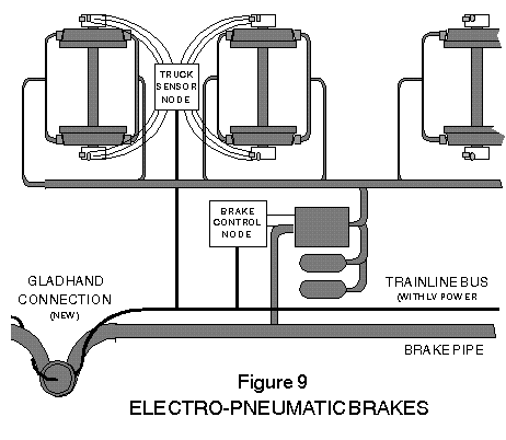
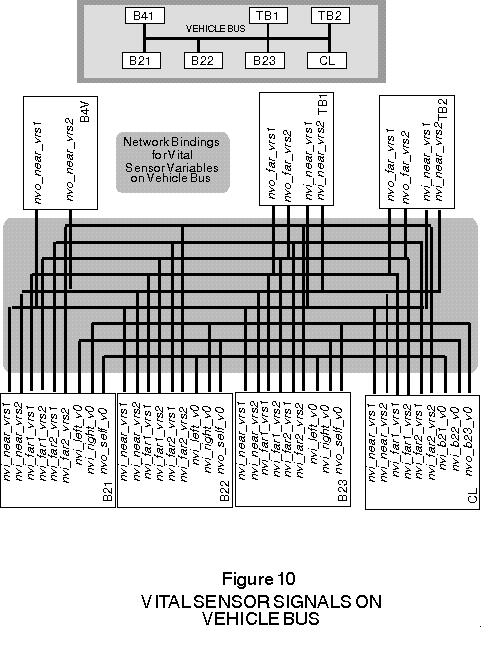
Figure 9 shows one of the most exciting opportunities for smart sensors in railway vehicles: electro-pneumaticly controlled brakes (ECP Brakes). Potentially all freight cars will have ECP Brakes and here's why. Traditional pneumatic brakes operate by releasing pressure from a 'brake pipe' which runs the length of the train. Each freight car has a service-brake reservoir that applies air pressure to tread brake cylinders according to the amount of pressure drop in the brake pipe. In other words, the train operator uses the pipe pressure as a pneumatic 'signal' to every car in the consist. When the brakes are to be released, the train operator closes a valve and the locomotive pumps the pipe pressure back up, which signals each car to open a valve so that the air pressure on the brakes is released to the atmosphere. The brake pipe is then acting as an energy delivery mechanism re-charging the reservoirs in each car. There are several problems with this system. One problem results from the fact that the brake pipe cannot do two things at once. Either it is sending a signal to apply the brakes or it is delivering the energy required to apply the brakes -- next time. One consequence is that, whereas the brakes can be applied at a graduated level, they must be released all at once. If an operator, for example, applies too much braking for stopping on a siding, the train will stop with the end car still on the mainline. After as substantial delay -- minutes -- to pump off the brakes, the operator must move the train again. The only other choice is to release the brakes, coast beyond the siding onto the mainline, and then back up. One feature of ECP Brake is graduated release. Now, the brakes are applied by allowing air to flow through the brake pipe forward to the locomotive. That takes a long time. Up to a second per car. With 'unit trains' of a hundred cars or more, that means it takes more than a minute and a half for the brakes to be applied throughout the train. Which is problem enough. But the brakes are applied starting at the car immediately behind the locomotive and then backward through the consist. The expression 'slack run-in' is self descriptive -- and the cause of many derailments and other accidents year after year. To avoid slack run-in, the operator typically increases power on the locomotive -- this, after having just initiated a braking action. With ECP Brake, a trainline bus takes over the signalling function from the brake pipe. The effect: simultaneous braking, which can cut stopping distance in half. {FootNote 4} Also indicated in Figure 9 is the 'gladhand connection.' One of the active proposals for ECP Brake is to integrate the trainline/power bus into a new version of the gladhand, which is presently used to link the brake pipe from car to car. The product faces a mechanical challenge: to achieve a reliable, genderless connection that will support a trainline bus in an unwholesome environment. Vitality & Sensors There are opportunities in railway vehicles for smart sensors in vital applications, but there are formidable problems to solve. Intelligent distributed control with its richness and flexibility in connectivity can contrib- ute to the solution. Binding is the key to vital delivery of sensor messages. Figure 10 shows triple-redundant nodes (B2x) connnected together through binding on the vehicle bus and set of nodes that are arranged to delivery sensor or command messages from the near end of the train and from the far end of the train. Another node operates as the command logger (CL).
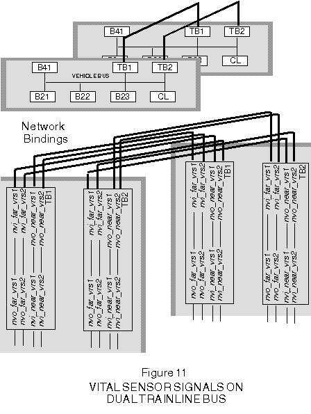
The implied connectivity and the bindings for the dual-redundant trainline buses are shown in Figure 11.
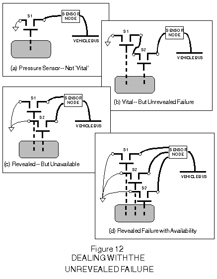
The cross-connections among the three B2x nodes enable the application of a self-disqualifying algorithm in each. Thus, if a given node detects disagreement with either or both of its neighbors, that node can 'tristate itself into oblivion.' {FootNote 5} Finally, there's the critical matter of making sure that failures are not kept secret from the decision makers, whether man or machine. In the node arrangement sketched in Figures 10 and 11, there would necessarily be replicated software that reports each failure of whatever kind: a sensor signal gone stale, a hard-over or rate-spike, a watchdog run-out, a disagreement over sensor measurements, self-disqualified node-gone-silent. Figure 12 shows a simple illustration of sensor issues including the 'unrevealed failure.' {FootNote 6}
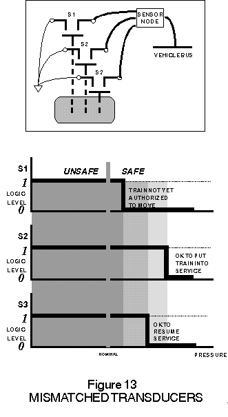
Figure 12 (a) is a sketch of a single pressure sensor connected to a node. Setting cost aside, no matter how reliable the device may be, the design cannot be considered vital. Assuming that train safety mandates pressure above some nominal value, a stuck switch would improperly allow the train to operate. Furthermore, during train operation, the failure is unrevealed. Figure 12 (b) has two connected switches. Depending on familiar considerations, the system may now be considered vital, inasmuch as a single failure will not allow the train to operate with pressure below nominal. Until the system is inspected with the switches isolated, however, the failure of one switch will be unrevealed, making the train vulnerable to a later single-point failure of the second switch. Figure 12 (c) separates the switches and permits the sensor node to compare them. The system is still vital. Moreover, a single-point failure will be revealed -- but which one is correct? It would be irresponsible to operate the train with a revealed disagreement between the sensors, which means a single-point failure has an adverse effect on service availability. Figure 12 (d) uses triple-redundancy to resolve the issue by 'voting.' The sensor node can be programmed to make a sound decision about operating the train despite any single-point failure. Furthermore, the failure is 'unconcealed' and can be reported without adversely impacting service availability. Some care must be used in designing the algorithm, however (see Figure 13). Inasmuch as the three sensors will almost certainly not agree exactly, the triple-redundant system produces four input cases -- even for normal operation. As the vessel is pumped up, the node will have plenty of time to observe those cases. The sensor node (or the downstream system) must be programmed to interpret the cases based on the present train state. Thus, a logic level of one on any two out of three inputs should allow the train to continue operation for the rest of the day; however, agreement from all three should be mandated in order to authorize the train to be taken out of the yard.
Now, suppose the three
pressure switches and the node were integrated into one product, a smart
sensor. If the whole algorithm is to be embedded into the sensor node,
then that node would need to have access to the train state as well. Given
a suitable network protocol, that will become a straight-forward design
option.
|
